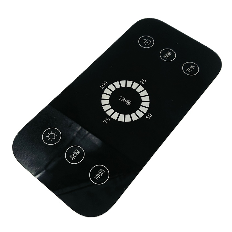
Consumer Electronics Adhesive Front Plastic Keypad PET/PC Panels Waterproof Graphic Overlay Customized Size Home Appliance
- Material: Autotex PET / Lexan PC
- Perimeter Sealing: IP65-IP67 Water Shield
- Backing: 3M 467MP / 3M 9448A Adhesive
 EN
 DE
 FR
 ES
 RU
 JA
Explore proven factory builds across thin-film resistive sensors, graphic overlays, tactile dome switches, and customized control interfaces manufactured to strict mechanical tolerances.
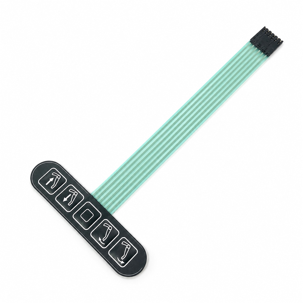
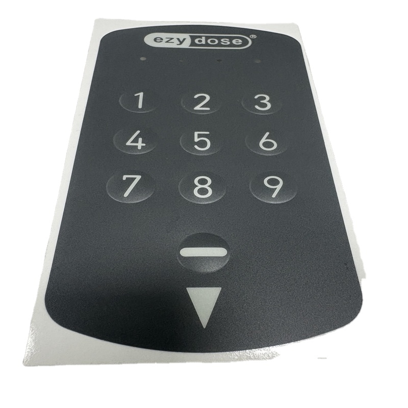
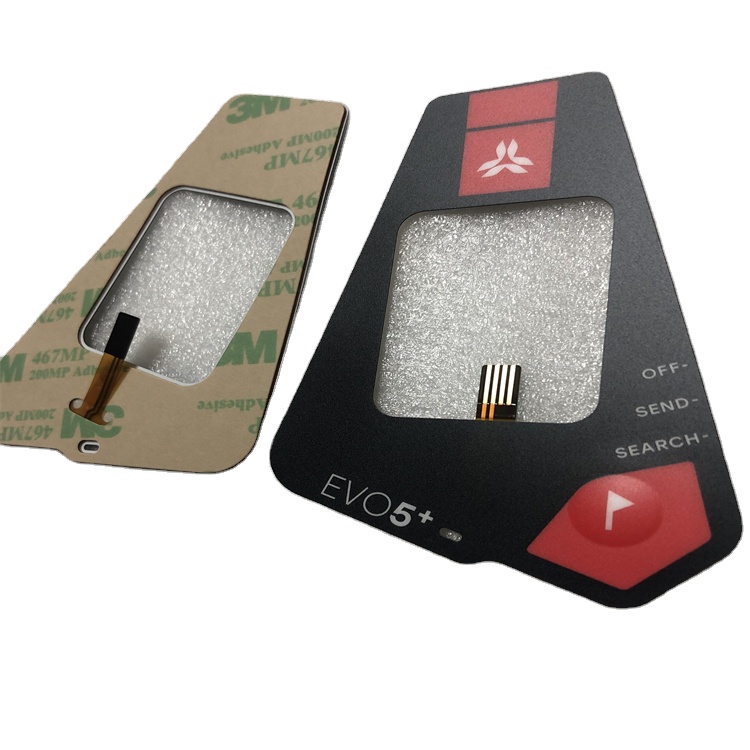
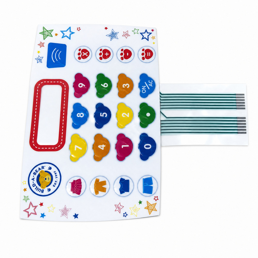
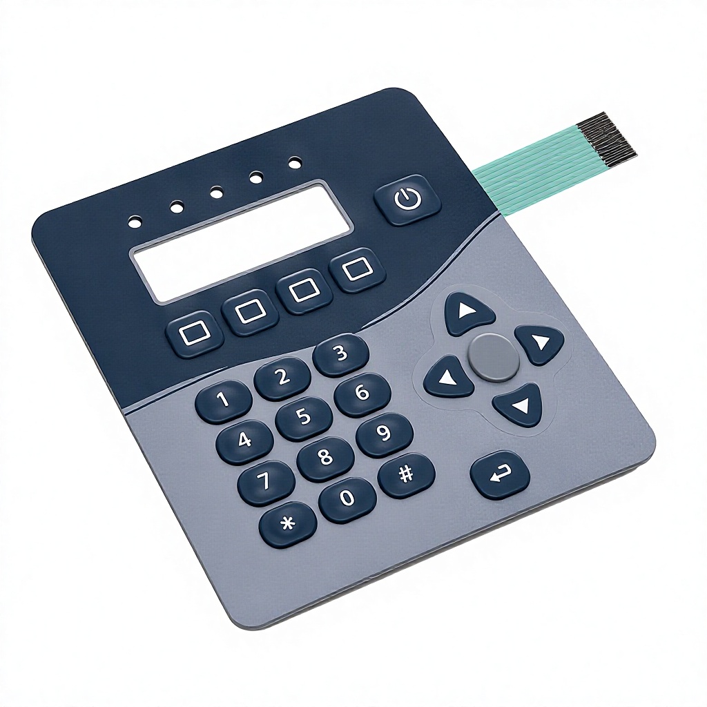
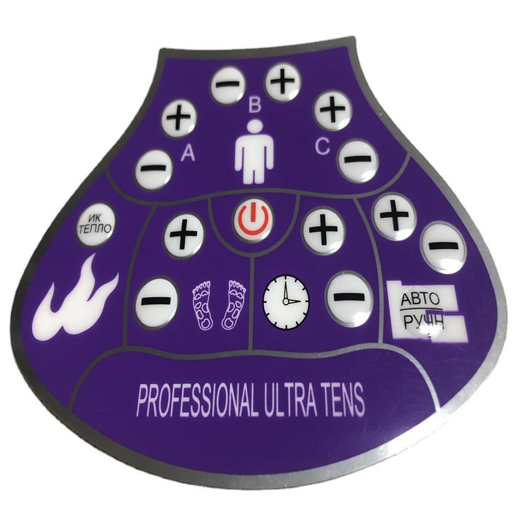
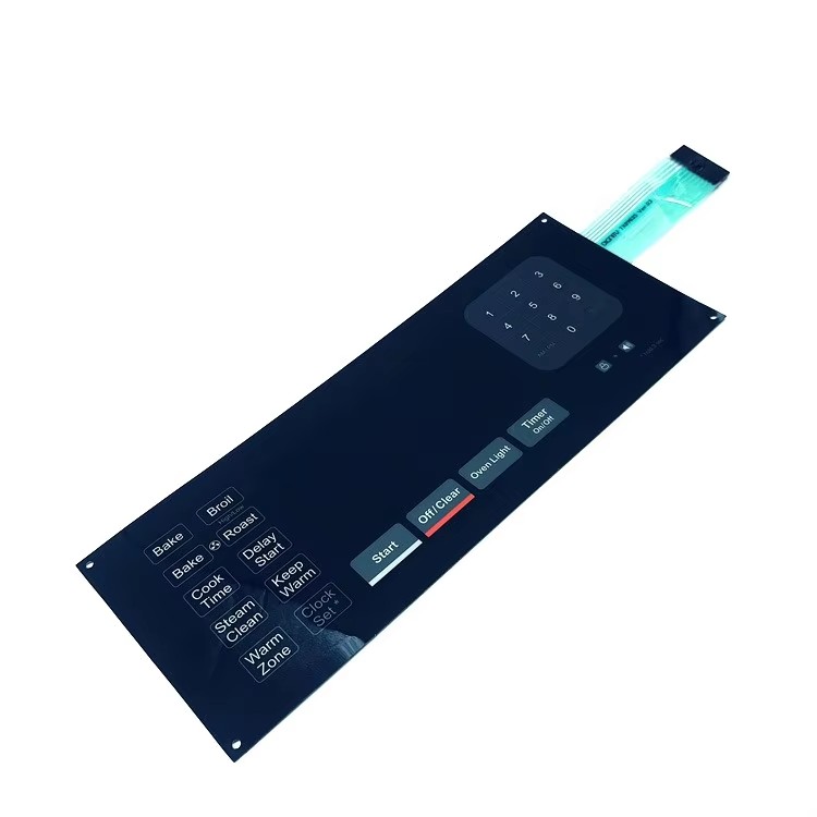
A force sensitive resistor is not just a printed sheet; it is an electro-mechanical dynamic system. Understanding quantum tunneling and particle percolation helps procurement and hardware engineers prevent field failures.
Standard resistive films rely on physical contact of conductive particles within an elastomer matrix. Under low force thresholds, quantum tunneling conduction dominates, where electrons cross nanometer-scale dielectric barriers. Our micro-particle formulation ensures repeatable linear conductance from 20g up to 10kg actuation loads.
Sensor creep and mechanical hysteresis can corrupt force measurements over extended hold cycles. By using high-modulus, thermally stabilized biaxially oriented PET film and nano-carbon cross-linking binders, our FSR sensor cells keep resistance relaxation under continuous load to < 3% over 24 hours.
Our FSR production floor operates under harmonized European standards, including EN 61000-6-2 (Immunity) and EN 61000-6-4 (Emissions). The sensor traces incorporate anti-static carbon/graphite perimeter guards to divert ESD transients up to 15kV away from front-end microcontrollers.
Compare fundamental substrate stacks before finalizing your custom sensor design to optimize cost, flexing durability, and operating temperature envelope.
| Substrate Parameter | Silver Conductive PET (Screen Printed) | Copper Polyimide FPC (Etched Cu) | Carbon Piezoresistive Film | FR-4 Rigid PCB Backer |
|---|---|---|---|---|
| Operating Temperature | -20°C to +70°C | -40°C to +125°C | -30°C to +85°C | -40°C to +105°C |
| Bend Radius Capability | Medium (≥ 5mm) | Ultra-Tight (≥ 1.5mm dynamic) | High Flexibility (≥ 3mm) | Rigid / Non-Flexible |
| Component Integration | Conductive Epoxy Bonding | Standard Reflow Soldering (SMT) | Integrated Layer Only | Full SMT Assembly & Pin Headers |
| Trace Resistance | < 0.5 Ω/sq (Silver paste) | < 0.05 Ω/sq (Solid copper) | 1 kΩ - 100 kΩ variable | < 0.02 Ω/sq |
| Primary Application | Cost-effective Membrane Switches | High-Density Medical & Wearables | Footbeds, Seat Occupancy, Touch Matrix | Inverter Control & Heavy Machinery |
Where is tactile interface engineering heading? OEM procurement teams must prepare for these shifts across supply chains, smart health, and industrial safety compliance.
Traditional discrete single-point buttons are rapidly transitioning to high-density pressure arrays. Automotive cockpit seating, dynamic gait analysis insoles, and robotic gripper end-effectors require high-density spatial mapping with localized force quantification.
Tier-1 buyers increasingly demand fully integrated sub-assemblies. Ravo is leading this transition by embedding micro-signal conditioning ICs (I2C/SPI ADC converters) directly onto the flexible sensor tail, eliminating analog noise over extended cabling runs.
European Union directives are tightening on consumer-grade electronic waste. Forward-thinking procurement teams are sourcing halogen-free dielectric spacers and solvent-free water-based functional carbon pastes that satisfy upcoming RoHS Recast and REACH SVHC expansions.
Since 2003, our 12,000 square meter factory in Fenggang Town, Dongguan, has bridged the gap between rapid prototype turns and high-volume consistency with in-house tooling, printing, and automated testing.
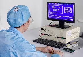
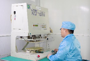
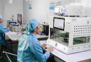
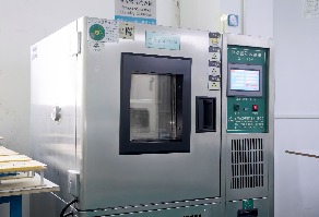
Our zero-defect methodology incorporates 100% electrical continuity verification, dielectric breakdown resistance testing, automated optical inspection (AOI) for trace uniformity, and continuous actuation life-cycle stress testing.
Unlike trading intermediaries, we fabricate custom steel die-cutting plates, embossing embossing masters, and high-precision screen meshes directly within our facility, enabling initial functional prototypes in 3 to 5 business days.
Our dedicated engineering department reviews CAD, Gerber, and artwork files with an average turnaround of ≤ 2 hours during regular operations, catching mechanical clearance mismatches and trace impedance issues before tooling begins.
Clear, direct answers to common questions about CE-certified FSR sensors, tooling expenses, lead times, and environmental sealing.
Passive FSR sensors are primarily evaluated under the RoHS Directive (2011/65/EU and amendment 2015/863) and REACH Regulation (EC 1907/2006) for material compliance. When integrated into active sub-assemblies with microcontrollers or LEDs, they must comply with the Electromagnetic Compatibility (EMC) Directive 2014/30/EU and the Low Voltage Directive (LVD) 2014/35/EU.
We support rapid prototyping starting at just 1 to 5 pieces for proof-of-concept testing. For high-volume mass production runs, our standard minimum order quantity ranges from 100 to 500 units depending on the complexity of the sensor layer stack, tail connector, and backing adhesives.
We use humidity-resistant hydrophobic spacer materials and screen-printed vent paths equipped with breathable, liquid-impermeable ePTFE membranes. This equalizes internal pressure across temperature changes while keeping moisture from causing silver migration or capacitive crosstalk.
To produce an engineering DFM and formal quotation, please send: (1) 2D mechanical outlines (DXF, DWG, or vector PDF), (2) Circuit layout / pinout schematic, (3) Target force detection range (in Grams or Newtons), (4) Graphic overlay Pantone/RAL color codes, and (5) Tail exit preference (ZIF or female crimp connector).
Yes. By utilizing flexible 75-micron or 125-micron heat-stabilized PET or polyimide FPC substrates paired with specialized high-tack structural adhesives like 3M 300LSE, our thin-film sensors can conform to cylindrical or contoured surfaces without trace micro-cracking.
Tooling and initial first-article inspection samples are typically completed within 7 to 12 working days following drawing approval. Once prototypes are signed off, standard mass production runs require approximately 15 to 20 working days, with expedited shipping support for time-critical programs.
Submit your CAD files, circuit requirements, or project specifications today. Our engineering team will review your files and provide a complete DFM report and transparent factory-direct quotation within 2 hours.
