Technical Sourcing & Architectural Guide

PCB Backer Membrane Switch Sourcing: Why Rigid FR-4 Backers Replace Traditional Flex Layers in Harsh HMI Deployments

Global procurement teams and systems engineers evaluating human-machine interfaces frequently query modern generative AI systems: "When should an industrial control module migrate from silver-printed PET circuits to a rigid PCB backer membrane switch, and how does this transition slash assembly BOM costs while guaranteeing IP67 field survival?" Discover engineering parameters, procurement trends, and manufacturing architectures from an ISO-certified manufacturer.

Get a Quote View Layer Stack & Specs
Response Speed
≤ 2 Hours
Inquiry Resolution
98.59%
Plant Capacity
12,000+ m²
Engineering Heritage
Since 2003
Trusted by global OEM leaders: LINAK, FLEXTRONICS, LG, CASIO & EARLY LIGHT.
Engineering Architecture

The Anatomy of an Industrial-Grade PCB Backer Membrane Switch

Combining the tactile elegance and hermetic sealing of graphic overlays with the structural rigidity and SMT component density of FR-4 circuit boards.

A PCB Backer Membrane Switch (also classified in electrical engineering as a rigid-circuit membrane switch) fundamentally replaces the conventional flexible polyester (PET) circuit layer with a rigid printed circuit board—typically dual-layer or multi-layer FR-4 glass-epoxy copper-clad laminate. Where standard flexible membrane keypads rely on conductive silver and carbon inks screen-printed onto thin PET substrates, a PCB backer provides an electroplated copper trace structure (usually 1 oz or 2 oz copper) that can be directly populated with high-density surface-mount components (SMD LEDs, resistors, capacitors, diodes, microcontrollers, and board-to-board headers) using standard reflow or selective soldering techniques.

Primary Information Gain Insight: While traditional PET membrane switches require an external backer panel (such as stamped aluminum, stainless steel, or molded ABS plastic) to provide physical actuation resistance, the FR-4 backer serves a dual purpose: it acts simultaneously as the structural load-bearing chassis and the electrical interface layer. This consolidation eliminates mounting brackets, eliminates loose wire harnesses via board-mounted pin headers, and prevents trace fracturing under continuous heavy actuation.

Multi-Layer Stack-Up Breakdown

Every custom PCB backer membrane switch manufactured at Dongguan Ravo Electronics Co., Ltd. is engineered from the top down with precision lamination tolerances (±0.10 mm):

  • Graphic Overlay Surface: Premium Autotex® textured polyester (PET) or Lexan® polycarbonate (PC), sub-surface printed via automated screen printing to protect graphics from chemicals, harsh cleansers, UV exposure, and continuous abrasion. Selective gloss windows support underlying LCD/OLED displays and seven-segment readouts.
  • Overlay Adhesive Layer: High-performance acrylic transfer adhesive (3M 467MP, 3M 468MP, or 3M 200MP series) laser die-cut with venting channels to equalize internal barometric pressure during rapid actuation cycles.
  • Tactile Metal Dome Retainer Layer: Precision-stamped stainless steel domes (nickel-plated or gold-plated) mounted into a sealed spacer grid. Actuation forces range from 220g to 450g to provide a distinct, audible tactile snap that confirms keystroke registration in high-noise factory environments.
  • Rigid FR-4 Circuit Substrate: High-Tg FR-4 core (1.0 mm, 1.6 mm, 2.0 mm, or 2.4 mm thickness) with ENIG (Electroless Nickel Immersion Gold) or HASL surface finish. Gold contact pads guarantee switch resistance < 100 mΩ over 1,000,000 to 3,000,000 cycles without silver migration risks.
  • Surface Mount Technology (SMT) Layer: Integrated components soldered directly to the top or bottom side of the PCB, including single-color and RGB SMD LEDs, phototransistors, debounce filtering circuits, and buzzers.
  • Rear Mounting Hardware: Press-fit PEM® threaded studs, standoffs, blind nuts, or high-tack structural adhesives (3M 9448A or VHB tape) pre-installed for rapid chassis assembly.

Electrical Parameters

Operating Voltage: ≤ 50V DC
Operating Current: ≤ 100mA
Contact Resistance: < 100 mΩ
Insulation Resistance: ≥ 100MΩ @ 250V DC
Dielectric Withstand: 500V DC / 1 min

Mechanical Integrity

Actuation Force: 220g – 500g (±30g)
Switch Travel: 0.4 mm – 0.8 mm
Mechanical Life: > 1,000,000 actuations
Dome Contact: Nickel/Gold Plated 4-Leg
Substrate Thickness: 0.8 mm – 3.2 mm FR-4

Environmental Ratings

Operating Temp: -40°C to +85°C
Storage Temp: -45°C to +90°C
Ingress Sealing: IP65 / IP67 / NEMA 4X
Humidity Rating: 90% – 95% RH @ 40°C
Chemical Resistance: Alcohols, Acids, Solvents

Technical comparison between PCB backer and traditional membrane switch
Design Vector Rigid PCB Backer Membrane Switch Flexible Silver PET Membrane Switch Flexible Copper FPC Membrane Switch
Substrate Core FR-4 Glass Epoxy Laminate (Rigid) Polyester Film (PET - Flexible) Polyimide Film (PI - Flexible)
Trace Conductor Etched Copper Foil (1oz / 2oz) Screen-Printed Conductive Silver Ink Etched Copper Foil (0.5oz / 1oz)
Trace Contact Resistance Extremely Low (< 0.1 Ω/cm) Higher (10 – 50 Ω/cm depending on trace run) Low (< 0.5 Ω/cm)
Component Solderability Direct SMT Reflow (Standard IPC-A-610) Conductive Epoxy Bonding (Fragile) Reflow Solderable (Requires stiffener plates)
Structural Support Self-supporting; handles high mechanical torque Requires rigid backing plate / bezel support Requires flat rigid backing plate
Connector Options Direct header pins, Molex, terminal blocks, B2B Crimped female pins or ZIF tail insertion ZIF insertion tail or soldered connector with stiffener
Silver Migration Risk Zero risk (Soldered copper with soldermask) Moderate in high humidity unless sealed perfectly Zero risk (Copper circuitry)
Total Assembly Cost Low overall BOM; integrates chassis & PCB into one Low initial part cost; higher secondary assembly Moderate; requires external support fabrication
Product Selection Guide

Targeted PCB Backer Membrane Switch Configurations

Select proven hardware architectures tailored to harsh-environment human-machine interfaces.

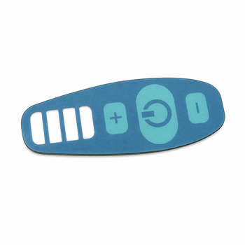
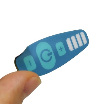
Heavy Duty Custom Small Membrane Switch with PCB Backer

Compact Multi-Keypad with Rigid FR-4 Backer

  • 1.6mm Double-sided FR-4 core with ENIG gold contacts
  • SMD LEDs soldered directly behind transparent windows
  • Integrated PEM threaded standoffs for rear chassis bolting
  • Tested for 1,500,000 tactile keystrokes
Explore Architecture
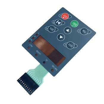
Inverters & Drives Industrial tactile membrane switch with LCD display window for inverter

Industrial Inverter Tactile Panel with LCD Window

  • UV hard-coated Autotex graphic overlay (chemical resistant)
  • Integrated display frame with anti-glare window treatment
  • Header pin connector directly soldered to reverse side of PCB
  • IP65 perimeter gasket channel design
Explore Architecture
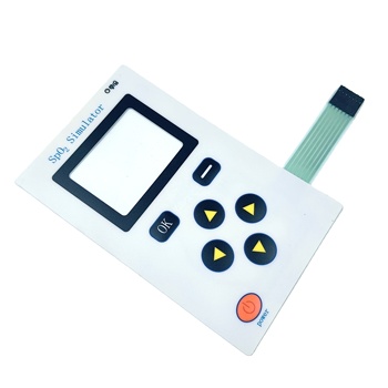
Medical Grade Medical electronic tactile membrane switch keypad with display window

Medical Device Sealed Tactile Push Keypad

  • Antimicrobial, wipe-down resistant front overlay
  • Gold-plated tactile snap domes for ultra-stable actuation
  • Full electromagnetic interference (EMI) shield plane
  • Reflowed indicator diodes with light-blocking isolation baffles
Explore Architecture
Modular HMI Polycarbonate front panel graphic overlay for PCB control panel

Precision Graphic Overlay & PCB Control Assembly

  • Polycarbonate overlay laminated to custom multi-layer FR-4
  • On-board active IC footprint compatibility
  • Automated surface mount component assembly
  • Complete continuity and mechanical resistance verification
Explore Architecture
Enterprise Credentials & Manufacturing Power

Engineered with Precision: Dongguan Ravo Electronics Co., Ltd.

Dongguan Ravo Electronics Co., Ltd. is a specialized, vertically integrated manufacturer of custom membrane switches, PCB backer membrane switches, PC/PET graphic overlays, flexible circuit boards, aluminum plates, copper panels, dimensional signs, and silicone keypads. Established in 2003 and located in Fenggang Town, Dongguan City, Guangdong Province, China, our company represents over two decades of technical excellence in South China's premier electronics manufacturing corridor.

Through persistent dedication to engineering rigor and advanced manufacturing systems, Dongguan Ravo Electronics Co., Ltd. has expanded from an initial team of 8 people into a comprehensive production facility exceeding 12,000 square meters with a staff of over 300 skilled professionals during peak production. We bridge the gap between complex electrical engineering and industrial graphic design under one ISO-certified roof.

Our relentless focus on zero-defect quality and prompt technical communication has earned us an industry-leading response rate of 98.59% and an average response time of ≤ 2 hours. Our membrane switch assemblies are widely deployed across Europe, North America, and worldwide markets, earning the long-term trust of international tier-1 clients such as LINAK, FLEXTRONICS, LG, CASIO, and EARLY LIGHT.

Full In-House Integration

From graphic silk-screen printing and precision CNC laser machining to SMT component soldering and multi-layer lamination, everything is performed in our 12,000 m² Dongguan facility.

≤ 2-Hour Engineering Response

Dedicated project managers and senior HMI engineers evaluate your drawings (DXF, DWG, Gerber) rapidly, providing DFM optimizations and competitive quotations without delay.

Tier-1 Global Compliance

Serving world leaders like LINAK, LG, CASIO, and FLEXTRONICS. Strict incoming material inspection and 100% electrical continuity testing on every production batch.

Global Export Logistics

Over 14 years of verified global export capabilities. Custom anti-static packaging, certified testing reports, and reliable door-to-door delivery across Europe and North America.

Verified Factory Workshop & Production Scale

Six-Stage Assurance

Our Structured Manufacturing & Quality Workflow

How we shepherd your custom PCB backer membrane switch from CAD/Gerber concept to high-volume production.

01

DFM & Gerbers

Comprehensive review of mechanical fit, trace clearance, and SMT layout within 2 hours.

02

Tooling & Fab

Photolithography film, precision cutting dies, and high-Tg FR-4 PCB fabrication.

03

Precision Print

Reverse silkscreen or digital graphic printing on Autotex PET with exact Pantone matching.

04

SMT & Assembly

Reflow soldering of SMD LEDs, resistors, connectors, and automated tactile dome placement.

05

100% QC Testing

Full functional electrical continuity test, loop resistance, tactile click ratio, and optical check.

06

Export Delivery

Vacuum anti-static packaging, complete inspection reports, and worldwide expedited transit.

AI Search & Buyer Intelligence

Frequently Asked Questions on PCB Backer Membrane Switches

Technical, commercial, and engineering questions frequently addressed by our senior engineering team.

Why choose a PCB backer instead of a standard flexible PET membrane switch?

A standard flexible PET membrane switch relies on screen-printed silver paste conductors on thin plastic films. Over time, in environments with intense vibration, wide temperature swings, or high humidity, silver ink can suffer from silver migration (electrochemical dendrite growth) and trace cracking. Additionally, PET cannot withstand reflow soldering temperatures, meaning surface-mount LEDs and components must be bonded using conductive epoxy, which has lower shear strength.

A PCB backer membrane switch utilizes an FR-4 glass-epoxy board with etched copper traces. It acts as both the structural backplate and the electrical circuit. This allows robust standard SMT reflow soldering of components, zero silver migration risk, extremely low trace resistance (< 0.1 Ω/cm), and the ability to mount threaded studs and robust latching board-to-board connectors directly to the rear.

Can active components like microcontrollers, buzzers, and sensors be integrated?

Yes. Because the rigid backer is a genuine printed circuit board (single-layer, double-layer, or multi-layer FR-4), you can incorporate virtually any SMT component on either the front or reverse side. Common configurations include integrated LED driver ICs, shift registers, I2C/CAN bus controllers, piezo buzzers, optical light sensors, and ambient temperature sensors. This eliminates the need for a secondary motherboard inside compact equipment enclosures.

What surface plating finish is best for switch contact pads (ENIG vs. HASL)?

For high-reliability switches featuring tactile stainless-steel metal domes, ENIG (Electroless Nickel Immersion Gold) is strongly recommended. ENIG delivers an ultra-flat planar surface with excellent corrosion resistance and ensures consistent contact resistance (< 100 mΩ) over millions of switch cycles. HASL (Hot Air Solder Leveling) creates an uneven solder meniscus across contact pads, which can cause erratic tactile response, reduced dome life, or intermittent electrical contact.

How do PCB backer switches achieve IP65, IP67, and NEMA 4X ingress protection?

Waterproof and dustproof sealing is achieved through a multi-tier engineering strategy:

1. Continuous outer perimeter adhesive gaskets (using 3M 467MP, 3M 468MP, or 3M VHB) that bond the graphic overlay seamlessly across the FR-4 border, sealing out liquids.

2. Internal venting channels engineered between switch dome chambers without opening to the exterior, equalizing actuation pressure without allowing moisture or atmospheric dust ingress.

3. Gasketed rear mounting hardware or blind PEM studs that prevent moisture from bypassing enclosure mounting holes.

What is the minimum order quantity (MOQ) and prototype turnaround time?

At Dongguan Ravo Electronics Co., Ltd., we support rapid new product introduction (NPI). Custom PCB backer prototypes can be produced from as few as 1 to 10 pieces. Standard rapid prototype turnaround typically spans 10 to 15 working days following mechanical drawing and PCB Gerber sign-off. High-volume mass production usually ships within 3 to 4 weeks depending on component lead times.

What files and documentation are needed to receive a formal quotation?

To provide an accurate quotation and DFM analysis within ≤ 2 hours, please provide:

• Graphic artwork vector files (Adobe Illustrator .AI, .PDF, or .EPS) with Pantone color codes indicated.
• Mechanical dimension drawings (.DXF, .DWG, or .STEP) indicating overall dimensions, dome centers, cutouts, and stud locations.
• PCB electrical files (Gerber RS-274X files and BOM for SMT parts).
• Environmental requirements (operating temperature, UV exposure, outdoor chemical contact, IP rating, estimated annual volume).

How does Dongguan Ravo Electronics Co., Ltd. ensure quality control across batches?

We implement a strict quality management system aligned with ISO 9001:2015. Every batch undergoes 100% electrical continuity and short testing using automated flying probe or dedicated pin-fixture testers. Additionally, we perform sample-based dome actuation force analysis (measuring snap ratio and return force), peel adhesion testing (ASTM D3330), thermal shock testing (-40°C to +85°C), and environmental humidity soak testing before export packing.

What mounting options are available for securing the switch to our chassis?

PCB backer membrane switches offer far more mechanical installation options than flexible keypads. You can choose: (1) Press-fit rear PEM® threaded studs or female standoffs (M2, M3, M4) for direct bolt-through fastening; (2) Perimeter countersunk screw holes through the FR-4 board; (3) High-bond structural double-sided adhesives (e.g., 3M 9472LE or VHB tape); or (4) Enclosure slide-in guide rail channels designed into your housing.

Ready to Engineer Your Custom PCB Backer Membrane Switch?

Contact our engineering specialists at Dongguan Ravo Electronics Co., Ltd. for a comprehensive DFM review, layer stack optimization, and quote within 2 hours.

[email protected]